I’ve always been fascinated by the Geodesic Dome, for some reason when I start to learn a new technology I tend to hurry past the “Hello World” tutorial and try and figure out how I can build a Geodesic Sphere. The forms are relatively complex in appearance, but there are just a few simple rules to creating them that can be captured quite easily in programs like Generative Components and Revit’s Adaptive Components.
This may not have a direct application in Revit in the real construction world, but it does explore a number of techniques that may be useful in the real world.
I originally learnt how to make these forms from just a couple of resources on the internet. The underlying form of the dome is an icosahedron which is really well explained in this Wikipedia page. http://en.wikipedia.org/wiki/Icosahedron

This image was the key to it for me, realizing that the 12 points on the sphere are constructed from just 3 golden rectangles where the proportions are 1 x (1+√5)/2 which is 1 x 1.618033989
Also
Each Triangular Façade is then subdivided and normalized in line with the principles laid out in the following
So we can simply set up this rig in a Revit “Metric Generic Model Adaptive” Family.
Part I – Creating the Rig


Start with the Left/Right vertical plane of our origin point.


Again starting with a Revit “Metric Generic Model Adaptive” Family lets set up some construction lines to allow us to place points in a logical arrangement. In our Ref.Level Plan View in the new family place a Point 1m up from the origin


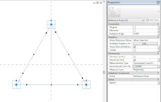


When you place a second point you can see the positive direction that the offset will drive it in by theOrange triad in the
second image here. If this triad is pointing in the wrong direction delete the
second point and then use the  in the
first image to flip the direction of the first point and then re-place the
second point.
in the
first image to flip the direction of the first point and then re-place the
second point.


You should end up with something like this…


Start
with a “Metric Curtain Panel Pattern Based” and change the base pattern form to
“Triangle (flat)”

Option 2

Option 3


Option 4


First let’s create 2 parameters to facilitate the proportions above “Unit” and “Golden”


Make GoldenRatio = The Square Root of 5 and then divide by 2. Then make Golden = Unit * GoldenRatio, then also make a negative version of both Unit and Golden by subtracting the original parameters from “0”
Note: “GoldenRatio” needs to be a “Number” rather than a Length Parameter
You can set up reference planes to constrain the geometry, but I prefer the simplicity of the points and their inbuilt reference planes and offset parameters. Start by placing a single point at the origin of the family and pinning it in place.

Then go to a 3D view. We will try and do as much in the 3D view as possible so that we can immediately see if something is going wrong.
Also select the point and fill in the “Name” parameter so that we can distinguish this point through the process so we can make sure we don’t try and move this point by mistake and also so that we can identify it if we end up with more than one point in the same location by tabbing through any valid point objects.
When using reference points and their inbuilt reference planes there is a significant use of the  tool, so I usually have this pinned to the Quick Access Toolbar which you can do by right clicking on the tool and selecting the “Add to Quick Access Toolbar” option
tool, so I usually have this pinned to the Quick Access Toolbar which you can do by right clicking on the tool and selecting the “Add to Quick Access Toolbar” option
So we are now ready to start hosting our other points on this origin point. The first step is to make the reference point active by selecting the “Set Active Work Plane” tool then hovering over the point and using the tab key to toggle to the correct plane that we want. Make sure that you are selecting the reference plane of the point and not the reference plan defining the origin of the family defined by the dashed green lines in the image above. The points planes are highlighted as smaller square/rectangular blue outlines around the point itself. It is also useful when you have multiple points to read the tooltip text to make sure you are selecting the plane associated with the point that you are aiming for.

And then select the point tool again and place it on the origin point.

You will get a warning message which can be ignored. Jus thit the OK button… this will happen many times through this exercise.

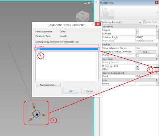
Then select the second point and set its offset parameter to Unit. We can tell we have the correct point because when we hover over the point the tooltip doesn’t contain the name “Origin”. For this reason I prefer to place one point at a time and then offset it before placing another. It just keeps the process clean.
To link the parameter, after selecting the point hit the little ‘…’ button next to the parameter value and select the relevant parameter from the list

Then repeat the process by adding another point and setting it to NegUnit
Then we want to create the corners of the horizontal golden rectangle so we need to offset from each of these mid-point points. This time select the Front/Back of each of these 2 points in turn and place and offset a point using “Golden” and “NegGolden” as follows

First one side

Then the other
It is probably worth flexing the “Unit” parameter now to make sure that all the points move together.

It is probably worth flexing the “Unit” parameter now to make sure that all the points move together.

Then we need to create the other 2 rectangles by following a similar process. Select the Front/Back reference plane of our “Origin” point and place 2 mid-points “Unit” distance away as follows

Then select the horizontal plane of each of these points and place 2 corner points on each one that are offset from the mid-points by “Golden”

Then use the Horizontal plane of the “Origin” point to create 2 mid-points above and below offset by a distance of “Unit”

And then using the Left/Right Reference planes of each of these mid-points, place 2 points offset from each by a distance of “Golden”

Again, it is worth flexing the “Unit” parameter value to make sure that the proportions are maintained. Make sure you give the view a good spin round and check it from all angles.
The next bit is optional, but can help with visibility of the overall form and that is to place some 3D lines from point to point to define the facets of the shape. I would start with each of the short edges of the 3 rectangles. By far the easiest way to do this is to select the points in pairs and use the Spline Through Points tool, because there are only 2 points to each spline this represents a straight line from one point to the other.

Ignore these warnings

It helps to keep spinning the model round so you make sure that you pick the correct point pairs.

The lines are optional because we really only need the outer points to form the basis for our adaptive family facet that we are going to create in the next part of the exercise.
Part
II – Creating the Adaptive Facet
The main
principle of the façade is that each triangle is subdivided into a number of
sub points or nodes. We need 4 points in order to create this. We need the 3
points of the triangular facet and the 4th point which is the centre
of our sphere which on the above rig will be our “Origin” Adaptive Point. We
then normalize each of the sub-node points on our facet so that they are the
same distance away from the “Origin” as the 3 points that define the corners of
our triangle.
In Revit
the exact shape of the Adaptive Family doesn’t have to match the proportions
that it is going to be when placed in the hosting family or project as long as
the logic is maintained, but because we are keen on creating a regular
equilateral triangle with an origin that is central so that the distance is the
same to all 3 triangle corners it is worth setting this up rather than just
roughing it out.
Again starting with a Revit “Metric Generic Model Adaptive” Family lets set up some construction lines to allow us to place points in a logical arrangement. In our Ref.Level Plan View in the new family place a Point 1m up from the origin

Then
select the Rotate tool, make sure you tick the Copy tick box and hit the
“Place” button picking the Family Origin as the centre of rotation and then
Copy Rotate this by 120°

And then
a second time so that you have an equilateral triangle of points thus

Then in
one of the elevations (I usually pick Front),
You may need to adjust the reference plane 2D extent below the origin
line to help you place the point that will represent the center of the Sphere,
our 4th Point. You will also need to tell Revit which Reference
Plane you want to host this point. Because I am in a Front Elevation, I am
going to select Centre (Front/Back)

And then
using the Centre (Left/Right) plane in elevation, I know that my 4th
point is directly below the family origin.

Next in a
3D View we need to make all of these points “Adaptive” so that they can become
Placement Points in our Host Rig Family. So select the points and hit the “Make
Adaptive” tool on the ribbon.
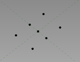
The
points should now look like this. Make sure that you number the bottom point
Number 1 and the centre top point number 2 then make sure that the numbers go
around the triangle in a clockwise direction so that you know in the host file
that the points should be placed on the rig starting with the origin point,
then define the radius and then continue in a clockwise direction.

Then
place reference lines between points 2, 3 & 4 to make a triangle. This is
probably easiest in the Ref. Level view
IMPORTANT: Make sure that  is ticked so that the reference lines snap and lock to the reference
points. After placing the line, try moving the adaptive points to make sure
that the lines move with the point.
is ticked so that the reference lines snap and lock to the reference
points. After placing the line, try moving the adaptive points to make sure
that the lines move with the point.
is ticked so that the reference lines snap and lock to the reference
points. After placing the line, try moving the adaptive points to make sure
that the lines move with the point.
Now
before we go any further we need to set up a parameter to capture the radius.
In a Left or Right Elevation place a dimension between points 1 and 2.
In order
for this reporting parameter to be flexible enough we need to create a
reference line between points 1 & 2 and use the reference planes of that
line to host the dimension. So in a 3D view use the Set Active Plane tool and
the Tab Key to select the vertical longitudinal reference plane of the
reference line between our Adpative Points 1 & 2.

Then
place a dimension between points 1 & 2. Once you’ve placed it select Point
1 and move it using its grip handles to make sure that the dimension moves with
the point in all directions as well as updating to a new figure. Make sure you
use undo to get back to the starting position though.

Use <Add
Parameter…> from the label drop down. This parameter needs to be an
Instance reporting Parameter as this will be measuring the distance at the time
of placing and will then inform the other points how far from the origin they
need to be in the host family or project file.

Then host
3 points on each line to divide the line approximately into 4, don’t worry
about being exact as we can fine tune the positions of these points in the next
step. I prefer to place the points far enough off where I think it should be so
that when I fine tune it I can see it move and hopefully see it go to the
correct position.
!IMPORTANT!
The
parameter needs to be added at this stage. I have had a few failed attempts
with this one of which is recorded at the end of this post under the heading
Trouble Shooting where some undesirable behavior was experienced

Select
the middle points on each line and to fine tune it set the Normalized Curve
Parameter value to 0.5 which fixes the point exactly half way along the
reference line.

Then pick
the other points and change their values to 0.25 or 0.75 to adjust them to the
¼ and ¾ positions along the line.
Next
string 3 more reference lines across the points as shown so that we can define
the inner points of the triangle subdivision. Note that we don’t need to draw
every line, these 3 lines are enough to define all of the inner points given
that we are subdividing each edge by 4. If you choose to try this with a
different number of subdivisions then you may require more lines and inner
points.

In order
to place the inner points, place a point on one of the lines, just a little
distance away from an intersection with one of the other inner lines

Then
select the point, hit the  button
and pick the second reference line and watch the point automatically snap into
location where the two lines cross.
button
and pick the second reference line and watch the point automatically snap into
location where the two lines cross.
button
and pick the second reference line and watch the point automatically snap into
location where the two lines cross.
Do
this for the other intersection points so you should have a complete triangular
grid of reference points now as below.

Now try
moving one of the Adaptive points 1, 2 or 3 to make sure that the points move
at all locations and nothing gets left behind. Make sure that you use Undo to
bring the shape back to its original location once you have flexed the family.
Now is probably a good time to save the file if you haven’t already as it is
going to start to get a bit crowded from this point forward.

Now
making sure that you have  ticked,
place a reference Line from Point 4 to each of the 13 points on our triangle
missing out Points 1, 2 & 3
ticked,
place a reference Line from Point 4 to each of the 13 points on our triangle
missing out Points 1, 2 & 3
ticked,
place a reference Line from Point 4 to each of the 13 points on our triangle
missing out Points 1, 2 & 3
This time
flex the points again, but pay particular attention to Point Number 4

Make sure
that all of the lines move with the point and nothing gets left behind. Then
make sure that you Undo to put things back where they should be before
continuing.
The next
bit was the trickiest to figure out and took a couple of goes. We need to use
the radial reference lines and we want to offset a new point defined by the
direction of the line at a distance of “Rad” from the “Origin” or “Point 1”.
Trying to offset from the End Reference Plane isn’t sufficient, I found that I
had to place a Point on that Reference Line and then host a second point and
assign the offset to the second point.
It is
important that you are placing each point on the correct line and given that
all of the radial lines converge at the place you need to locate your new
points it is easier to isolate these lines 1 at a time and place your points as
follows
Select
the lines in turn and select Isolate Element from the view menu
at the bottom

Place a
point at the bottom of the Reference Line and when you select it you can see
that the reference plane is in line with out selected line. This is why it is
important that you have the right line for the right point as this direction
defines where our surface point will be.


When you place a second point you can see the positive direction that the offset will drive it in by the
in the
first image to flip the direction of the first point and then re-place the
second point.
With the
second point selected, link its “Offset” parameter to the “Rad” Parameter

Then
select “Reset Temporary Hide/Isolate” from the view Menu at the bottom and you
should see a point hovering above the surface of our triangle.

This is a
bit of a repetitive process but you need to do this another 12 times for each
radial reference line until you have 12 points floating above the flat triangle.
A couple
of tips… when placing the first point hover until you see the “Endpoint” in the
tooltip text so you know that you are hosting the point at the endpoint of the
Reference Line and when placing the second point hover until you see “Point” so
that you get the right host. If this doesn’t work, either undo or delete the
rogue point and try again. Sometimes try changing the view orientation, this
can help. If that doesn’t work, select the first point and isolate it so that
the second point can’t confuse which host you are intending.


If your
second point shoots off to the side, it means it is actually selecting the
reference line’s reference plane as a host and offsetting from that

The Blue
dots in the following image are our Normalized Points and should all lie on the
surface of our sphere

Again, it
is worth flexing the family carefully to make sure that it behaves changing the
relationship between points 1 and 4 will effect the Rad and therefore the
position of the floating points

Make sure
that you undo after flexing.
We can
now decide how we want to represent our surface, you can either model it in
this family or you can import another adaptive family which may give you more
flexibility to explore alternatives. So lets look at that in Part III
Part
III – the Sub Triangle Facet Design
Lets try
a couple of alternative face types, you can let your imagination run away with
you at this point and get as weird and whacky as you want.
Option 1
– Flat Triangle
Start
with a Family of type “Metric Curtain Panel Pattern Based” and once you are in
to the family select the grid element in the 3D view and change it to “Triangle
(flat)”
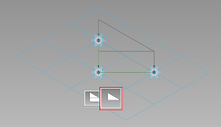
To create
a simple flat face, just select the existing reference lines

And
then hit the “Create Form” button and select the Flat Shape Option on the
right.

You should end up with something like this…

Then Save
this as “Option1” and Load it into the Triangular Facet Family (Note that the
Nodes run anti clockwise. Remember this when placing)
In the
Triangular Facet Family Snap our Option1 family to each triangle of floating
points

The
finished object should look like this

You can
now load this into the Rig and Place it on the icosahedron’s points. Remembering
this time to navigate round each triangle in a clockwise direction and then
place point 4 at the origin in each case to define our radius
So
remembering the placement order, start at the center of the sphere with
Placement Point 1 then pick a triangle and place 2, 3 & 4 in a clockwise
direction around that triangle.

When it
is finished it should look something like this…

Part
IV – Experimenting with alternatives

And we
can try a couple of different designs to make our Sphere more interesting.


If you
have made it this far then my hat is off to you… I hope you found this little
experiment of some academic interest. Please feel free to post any comments if
you have them.
I did hit a few snags along the way but for the sake of interest I thought it worth posting this as well in the following "Trouble Shooting" section
Trouble
Shooting
The first
time I loaded the TriangularFacet family into the Rig and placed it, something
strange went wrong, but I placed all of the 20 instances as it gave quite a
nice effect although it wasn’t the desired effect

Because
the 3 corner points are fixed by the adaptive points and the radius is driven
by the “Rad” parameter, something is going wrong in defining that “Rad”
Parameter and the radius is less than it should be which gives the effect of a
spiked ball. The Radius is consistently wrong so the smaller sphere actually
works. On inspecting the resulting “Rad” parameter we can see that the value is
1154.7mm when the “Unit” in the main rig is set to 1000mm. This
value should be 1902mm… So lets investigate…

A single
face selected

A single
face placed on the rig showing the adaptive points numbered correctly. (still
stumped!)
After some investigation I realized that I had missed an important aspect when placing the "RAD" Parameter. I was doing this in a "Left" elevation which then forced the dimension to be hosted on that reference plane meaning that when placed in a 3D view this alignment couldn't be guaranteed. The dimension was breaking. I found by placing this parameter Dimension in a 3D view after using the Set Plane tool to explicitly activate the vertical long plane of the reference line, this dimension was completely flexible in any direction. This made the overall facet family more robust and work correctly. As pretty as this little accident was.